Basic Crate Mould Constructions
Two of the most critical steps in development of a molded plastic crate are the original product design.and mold engineering. Obviously, tlie two steps are not independent, and the product designer should keep the crate moldmakers constraints in mind. However, although the cost of the crate mould is often substantial, it is often only a small part of the total development cost. Total costs include the cost of making and testing prototypes, marketing, and inventory before the product can be sold.
Two of the most critical steps in development of a molded plastic crate are the original product design.and mold engineering. Obviously, tlie two steps are not independent, and the product designer should keep the crate moldmakers constraints in mind. However, although the cost of the crate mould is often substantial, it is often only a small part of the total development cost. Total costs include the cost of making and testing prototypes, marketing, and inventory before the product can be sold.
The first step in crate mould making engineering is to have complete product drawings, including all tolerances (preferably using geometric tolerancing to reduce ambiguity), draft angles, surface specifications and exact polymer to be used. A prototype or a 3-D CAD model can be extremely helpful. If the part is complex or unusual in shape, computer simulation of the mold-filling process can be provided using commercially available software. These programs may help reduce problems encountered during molding by providing predictions of shrinkage and residual stress formation, guiding the design of runners and gates, and pointing out potential problems to experienced molders.
The next step is to decide on the type of machine and mold to be used based primarily on the ordering quantity and production rate required. This determines the most economical number of mold cavities and the desired cycle rate. Part design determines location of parting plane(s), gates, runners, ejection details, and side cores (if any). At this time, any postmolding operations are decided. Finally, this also is the time to select potential moldmakers if the mold is not to be made in-house.
Two-Plate crate Moulds
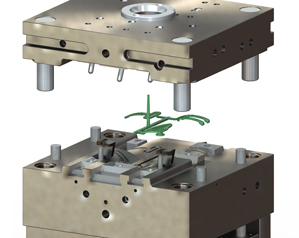
Figure below shows the main features of a two-plate injection mold, the simplest and most common type. Cooling in the cavity inserts and core inserts is not shown, but should be provided. Pressure and temperature transducers are not shown, but should be strategically located in accord with good instrumentation practices. The knockout bar, in this design, is stationary so that when the mold opens the ejector plate does not move and the parts are lifted off the cores. A Z-shaped sprue puller pulls the sprue and runner off the stationary A plate. The sprue puller moves out of its hole during mold opening and the sprue can fall off with the parts. This drawing shows edge gates into the cavities.
Three-Plate crate Moulds
Figure shows a multicavity, three-plate mold with center-gated cavities. The main puipose of this design is to automatically separate runners and gates from the parts during Crate Mould opening. In the illustrated design, plastic is injected through the sprue bushing into trapezoidal runner channels cut into the runner plate. The wide side of the trapezoids face the A plate so that they release during mold opening. When the mold opens, A and B plates move together, possibly with the aid of an auxiliary latch mechanism, and the mold separates along parting plane P-l. This breaks the sprue, but the runners remain with the A plate. Continued mold motion separates the A and the B plates at parting plane P-2 and releases the runners and gates. The molded parts remain on the cores until they are ejected in the usual way by the ejector plate.
Three-plate molds also are used when it is necessary to provide center gates or multiple gates for proper flow into cavities. For thin-walled parts having large flow length/thickness ratios, two or more pin gates directed into the part may be needed to obtain equal flow distances and avoid flow distribution problems. The three plate mold is well suited in these cases.

In complex molds,it is important that mold parts be sturdy and fitted carefully to ensure that the sequence of steps proceeds smoothly, without cocking and binding. Stresses induced by clamping forces on mold parts can be high enough to cause appreciable distortion. They should be checked using conservative strength of materials analyses to ensure that mold part deflections do not cause out-of-tolerance moldings. In an extreme case, excess clamping conceivably can deform parts of the mold enough so that elastic springback at the time of ejection can be greater than the shrinkage of the plastic, resulting in jams. In multicavity family molds, where the cavities have different projected areas, it is important to try to locate cavities so that cavity forces are as equal as possible to balance pressure loads on the mold. Perfect balance occurs when the sum of the moments of the cavity forces about the center of the mold platen equals zero.you could find more about crate mould making information :http://www.myplasticmold.com/packaging-food-beverage-plastic-mold