Categories
Mold Design

Details of Mold Design

Details of Mold Design

After the basic plastic mold design, number of cavities, and machine have been chosen, numerous design engineering decisions still remain. a guide to the sequence of steps in design of an injection mold is following:

  • Given Part design
  • Order quantity – and schedule’s Target production costs
  • Select molding machine
  • Estimate cycle time
  • Calculate optimum number of cavities
  • Select type of mold Preliminary cavity layout Runner and gate layouts
  • Recheck runner and gate design Layout cooling channels for cavities and cores Finalize cavity placement
  • CAE
  • Fill analysis Shrinkage and cooling analysis
  • Mold layout and details
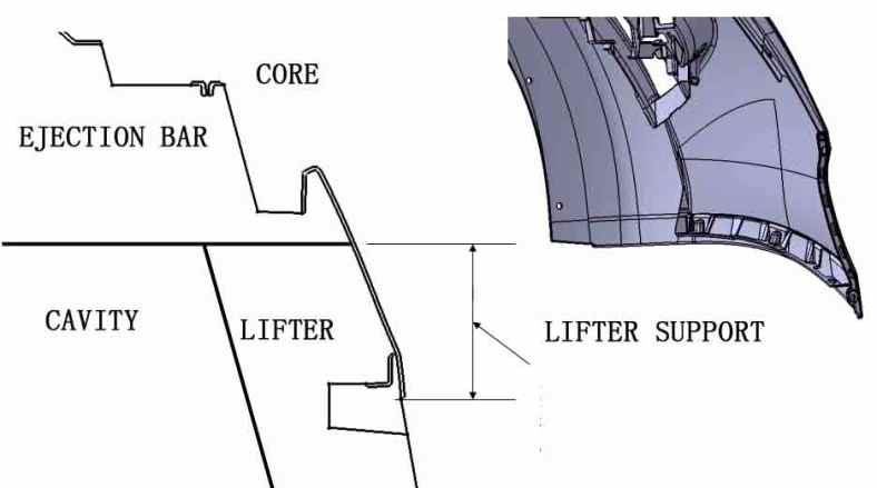
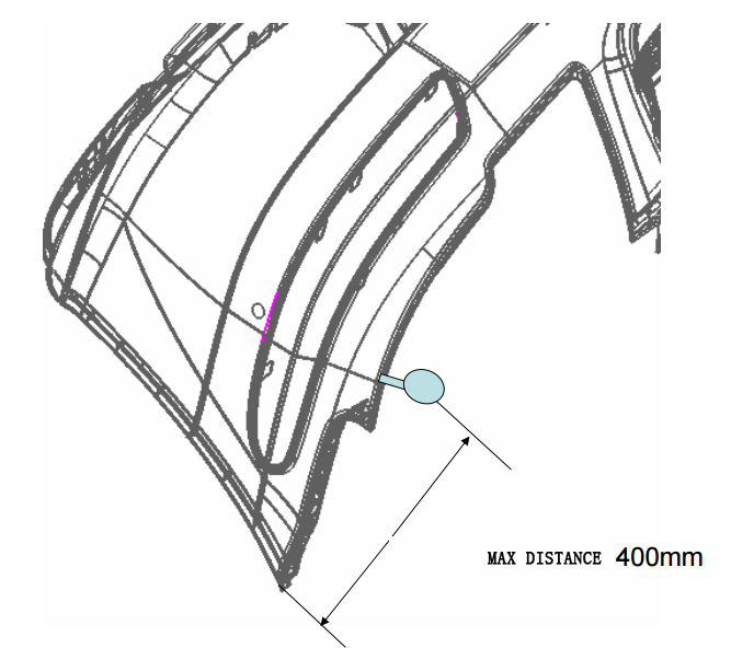
  • Select mold base Layout side core motions Layout ejection and venting Check mold parts for strength Final drawings and bill of materials
  • Plastic mold making
  • Trial run
  • Set starting operation conditions Optimize operation conditions

Sprue, Runner, and Gate Systems

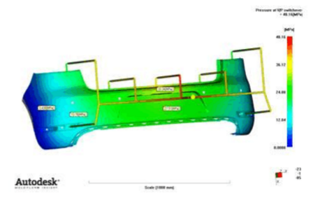
The purpose of the sprue, runner, and gate systems is to conduct melt uniformly and with minimum pressure and temperature drops to each cavity, or to the furthest point in a large single cavity. Uniformity of flow means essentially equal flow rates through each gate. This implies equal pressure at the exit from each gate, assuming that all cavities are identical. In the case of a family plastic mold injection, the total flows may be different to each cavity, but, in a perfectly balanced design, the various cavities will be completely filled at about the same time. When a cavity pressure control system is used, switchover from injection to holding or packing is controlled by a pressure transducer in one of the cavities. This system works well when all cavities are filled at about the same time. However, if one cavity fills early and its gate freezes before the packing phase is initiated by the pressure sensor in another cavity, it may result in defects associated with insufficient fill and low density. Overpacking also may occur if flows are not balanced. Overpacking would be evidenced by ejection problems and by internal stresses in the moldings.

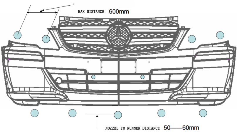
Therefore, the first step in multicavity design for plastic mold manufacturers is to lay out a balanced flow arrangement, i.e., one in which flow rates to each cavity are such that all cavities fill in about the same time. If all cavities are the same then this reduces to having equal pressure drops from the sprue to each gate exit. In simple cases, a naturally balanced layout has equal lengths and sizes for all flow channels; this also assumes that cavity plate and core temperatures are essentially uniform. Numbers of cavities for naturally balanced molds are 2, 4, 6, 8,16, 18, 24, 32, 48, 64, 72, 96, and so on, and any circular layout about a central point. Enough space should be provided between cavities to allow sufficient cooling for uniform mold temperatures. In more complex cases, the mold is either partially balanced or artificially balanced

runner

Artificially balanced runner systems, designed using a computer or by experimentation, use runners with varying cross-sectional areas and equalized pressure drops. However, such systems have smaller processing windows because of complex interactions between rheology and heat losses from the runners. For very small parts, it is especially important to have natural balance for stability; the recommendation is to use small runners with high pressure drops. To minimize temperature fluctuations, such molds are preheated for startup and heat is supplied by the circulating coolant. There is not much heat input from the injected melt with small parts.

Sprue bushings are generally catalog items, but it is worthwhile to examine the different types available, in light of molding requirements. The main problem in the sprue area is to accommodate the large temperature difference between the nozzle and the sprue. The nozzle must be kept above melt temperature and the sprue, in a cold-runner system, must be close to mold temperature. Keeping the sprue as small as possible, providing a separate nozzle heating band, thermally isolating the sprue, or changing to a hot-runner design are all solutions to sprue area problems.

Considering other constraints on the mold design, runners should be as short and streamlined as possible. Runner sizes are determined by compromise. Large runners may fill cavities faster and more reproducibly from cycle to cycle and, hence, tend to produce higher quality parts. However, excessively large runners slow down the cycle by requiring longer cooling times, produce more regrind, and increase the required clamping force. (These objections to large runners do not necessarily apply to hot-runner molds.) Various shapes of runners are used, the most common being the trapezoidal or modified trapezoidal .

plastic mold gate

Runner and gate sizing for a multicavity mold is an iterative design procedure. First, a trial set of lengths and diameters of the runners is assumed. Then, shear rates, shear stresses, and pressure drops are calculated and compared with allowable or desirable pressure drops, as in the following example. Viscosity/shear-rate curves for the polymer at process temperatures are necessary data. Commercial software is available for these calculations.

Categories
Antistatic Materials plastic mold company

Antistatic Materials

Antistatic Materials

blow molding industryTwo specific problems that may be lessened or corrected by the use of antistatic materials are found in the blow molding industry. The first deals with the presence of contaminating chips within blow-molded containers, and the second deals with unsightly dust collection on blown polyethylene parts on store shelves.

Particles of polyethylene that are forced into a container by such operations as reaming pose a rather serious problem in some container operations. Removal of the chips is costly and even the use of high pressure air does not always do the job. Due to the presence of 

static in a material such as polyethylene, these particles cling tenaciously to the blown part. The presence of these chips will cause plugging of nozzles in the bottle filling line. The smaller the filling nozzle the more serious the problem. The presence of an antistatic additive in the raw material will lessen the grip of the contaminate.

Dust collection on such plastics as polystyrene and polyethylene due to static attraction is much more pronounced than on materials that absorb moisture, such as cellulosics, and dissipate static electrical charges. Patterns are actually formed from dust that is pulled to the container or part from the surrounding air. The proper use of antistatic materials to overcome this problem is based on the incorporation of the product in the raw material. The additives are used in low concentration and therefore, must be uniformly dispersed through the plastic.

It is recommended that thorough testing be conducted on critical blow-molded parts applications before a final decision to use antistatic materials is made. The degree of exudation of the additive may alter treatment and decoration techniques of the part. The effect of the additive on stress-crack resistance must also be investigated.

The following antistatic agents are in use today: An-stac M and 2M Armid O Nopco 1009-C; Slip-EzeSequestrene NA4 “Zelec” NKGlyceryl Monosterate ENalquat G-9-12 and G-8-12. In general it is suggested that the antistats be added at the 1 part or 1 per cent level.

Categories
bumper mould

Automotive bumper mould


Automotive bumper mould

We could supply different kinds of the bumper mould with P20 and 2738 steel ,especially for the hot-runner and runner-less car bumper mould.

Runner-less or Hot-Runner of  Bumper Mould

When the plastic melt is thermally stable, it is possible to completely eliminate the need to regrind runners by using runnerless molds. One common type is the hot runner mold. In this bumper mould, the plastic is injected into an insulated runner plate that is kept slightly above melt temperature by a separate set of electric cartridge heaters and then through the runner channels and insulated nozzles into each cavity . In effect, this is a runnerless operation since there is no runner regrind. The hot runner plate is thermally insulated by an air gap.

Bumper Mould gate position

Hot-runner car bumper moulds have numerous advantages as a consequence of elimination of sprue and runner regrind. There is no material loss or contamination from regrinding and no extra cost in blending regrind with virgin resin for automotive company. There is no degradation of polymer, especially in optical and electrical properties, due to regrind usage. No energy is wasted in regrinding or in melting and cooling regrind. There is an effective increase in shot capacity and reduction in required mold-opening stroke. Cold runners have a tendency to catch on other mold parts during ejection, and this problem is eliminated. The bumper mould fills faster and balanced flow to the cavities is more readily accomplished.

To control drool and yet prevent freezing, hydraulically operated gate valves or valve gate systems have been developed . Valve gates are compact hydraulic cylinder/valve pin assemblies for positive individual gate shutoff. At a preset time, the hydraulic cylinders retract at each gate, permitting melt flow. Secondary timers set the positive closure of each valve to occur after optimum preset fill time has expired. This eliminates overpacking or underfilling at each gate. The system manifold and nozzles are temperature controlled to prevent thermal degradation of the melt. This complex system helps control cavity filling and end bumper product properties, especially for large, multigated parts and family moulds. Family moulds make different parts for a common assembly, and inherently have unbalanced flow. Valve gate systems can be adjusted to compensate for unbalanced flow and to run with minimum rejects in these situations. This is vital where regrind is not allowed because of rigid product specifications, such as in medical or optical products.

bumper mould maker

A simple alternative to heated hot-runner bumper moulds is to provide sufficient thermal insulation in the runner plate to keep the plastic from freezing. In an insulated runner mold a low thermal conductivity plastic skin, formed toward the end of injection next to the surface of the runner walls, insulates the bulk of the plastic flowing through the channel. The diameter of the runner is about twice that for a cold-runner system. One disadvantage is that machine stoppage for 15 s or more may result in runner freezing, requiring partial disassembly of the mold to remove the runner.

bumper mould company

Runnerless bumper molds have become popular for long production runs where extra mold cost and setup time can be absorbed by bumper mold maker . Valve gate systems are susceptible to contaminants in the melt stream that can clog nozzle valves. The three-plate mold is an alternative when simplicity and lower cost are important, and where runner regrind is not excessively costly.


Categories
Crate Mould

Crate Mould Constructions

Basic Crate Mould Constructions

Basic Crate Mould Constructions
Two of the most critical steps in development of a molded plastic crate are the original product design.and mold engineering. Obviously, tlie two steps are not independent, and the product designer should keep the crate moldmakers constraints in mind. However, although the cost of the crate mould is often substantial, it is often only a small part of the total development cost. Total costs include the cost of making and testing prototypes, marketing, and inventory before the product can be sold.

The first step in crate mould making engineering is to have complete product drawings, including all tolerances (preferably using geometric tolerancing to reduce ambiguity), draft angles, surface specifications and exact polymer to be used. A prototype or a 3-D CAD model can be extremely helpful. If the part is complex or unusual in shape, computer simulation of the mold-filling process can be provided using commercially available software. These programs may help reduce problems encountered during molding by providing predictions of shrinkage and residual stress formation, guiding the design of runners and gates, and pointing out potential problems to experienced molders.

The next step is to decide on the type of machine and mold to be used based primarily on the ordering quantity and production rate required. This determines the most economical number of mold cavities and the desired cycle rate. Part design determines location of parting plane(s), gates, runners, ejection details, and side cores (if any). At this time, any postmolding operations are decided. Finally, this also is the time to select potential moldmakers if the mold is not to be made in-house.
Two-Plate crate Moulds
Figure below shows the main features of a two-plate injection mold, the simplest and most common type. Cooling in the cavity inserts and core inserts is not shown, but should be provided. Pressure and temperature transducers are not shown, but should be strategically located in accord with good instrumentation practices. The knockout bar, in this design, is stationary so that when the mold opens the ejector plate does not move and the parts are lifted off the cores. A Z-shaped sprue puller pulls the sprue and runner off the stationary A plate. The sprue puller moves out of its hole during mold opening and the sprue can fall off with the parts. This drawing shows edge gates into the cavities.
crate mould making

Three-Plate crate Moulds

Figure  shows a multicavity, three-plate mold with center-gated cavities. The main puipose of this design is to automatically separate runners and gates from the parts during Crate Mould opening. In the illustrated design, plastic is injected through the sprue bushing into trapezoidal runner channels cut into the runner plate. The wide side of the trapezoids face the A plate so that they release during mold opening. When the mold opens, A and B plates move together, possibly with the aid of an auxiliary latch mechanism, and the mold separates along parting plane P-l. This breaks the sprue, but the runners remain with the A plate. Continued mold motion separates the A and the B plates at parting plane P-2 and releases the runners and gates. The molded parts remain on the cores until they are ejected in the usual way by the ejector plate.
Three-plate molds also are used when it is necessary to provide center gates or multiple gates for proper flow into cavities. For thin-walled parts having large flow length/thickness ratios, two or more pin gates directed into the part may be needed to obtain equal flow distances and avoid flow distribution problems. The three plate mold is well suited in these cases.
mold_header

In complex molds,it is important that mold parts be sturdy and fitted carefully to ensure that the sequence of steps proceeds smoothly, without cocking and binding. Stresses induced by clamping forces on mold parts can be high enough to cause appreciable distortion. They should be checked using conservative strength of materials analyses to ensure that mold part deflections do not cause out-of-tolerance moldings. In an extreme case, excess clamping conceivably can deform parts of the mold enough so that elastic springback at the time of ejection can be greater than the shrinkage of the plastic, resulting in jams. In multicavity family molds, where the cavities have different projected areas, it is important to try to locate cavities so that cavity forces are as equal as possible to balance pressure loads on the mold. Perfect balance occurs when the sum of the moments of the cavity forces about the center of the mold platen equals zero.you could find more about crate mould making information :http://www.myplasticmold.com/packaging-food-beverage-plastic-mold
Categories
plastic mold company

How to Look for in PET preform Mold Supplier

PCO28MM preform mold

How to Look for in PET preform Mold Supplier

When engineering comes to purchasing with a requirement for PET preform molds , many times the purchasing person isn’t knowledgeable enough about purchasing PET preform molds to know where to go for the requirement. In some companies, project or product engineers are in charge of finding a mold manufacturer, but even then there are questions about what to look for in a mold supplier.

Many purchasing people will go online as a first step, and there they will find a plethora of mold manufacturers. So how to pick the right one for the job? Most mold shops have similar machine tool capabilities and CAD/CAM software systems. Where the differences come into play are the mold types in which different shops specialize. Some of the types of molds include:

• Insert Molds: molds which accommodate inserts (either robotically or manually inserted) which the plastic is molded around to eliminate secondary or post-molding operations.

• Overmolding molds: molds which accommodate placement of a substrate part over which another material is molded, i.e. an ABS substrate with a thermoplastic elastomer (TPE)

• Two-shot molds: mold which are built to accommodate multi-material molding or multicolor molding, such as an automotive tail light, which might require both red and orange polycarbonate material to be molded for a complete tail light.

• Rotary Stack Molds: molds that produce multiple parts that require multiple processes. The mold is built in a “cube” and after each process the mold rotates 90 degrees for the next process. This is for highly complex components requiring both multi-material or multiple steps to complete, but the result is a final, completed and assembled unit. Eliminates secondary operations, multiple steps after molding or multiple molds to make a complete unit.

• Unscrewing molds: molds that accommodate threaded parts such as screws, caps and closures, and generally have either id or od threads.

Some  molds  manufacturers specialize in very large-sized molds such as those that would be used for bumpers on cars or trucks. Some specialize in very small molds for micro-molding. Most fall somewhere in between, and can generally handle molds that fit up to a 500-ton injection molding press. Mold manufacturers also have market niches with which they have become well-acquainted with such as extremely high-cavity molds (128 cavities for example) for the packaging industry; or smaller cavitation molds for the medical industry; or very aesthetic molds for the cosmetics packaging industry.

Mold manufacturers develop certain areas of expertise over their years in business, and generally are more successful when they stick to those areas of expertise. While it’s not impossible that a moldmaker that has only built smaller, 2, 4, 8 or 16-cavity molds could successfully build a 96-cavity medical mold, it’s best to find a mold manufacturing company that has a track record in building the type of mold that the OEM requires to help ensure everyone’s success.

For example, a mold manufacturer might be good at large multi-cavity molds, but has never built an unscrewing mold for a cap application. There are mold manufacturers that specialize in building unscrewing molds and have built hundreds over the years. The opportunity for a successful build for a large, multi cavity unscrewing mold from a shop experienced in this type of mold is much greater than one which has never built an unscrewing mold.

If the price sounds too good to be true…

You’ve heard it before – it probably is. Mold manufacturers do not have “standardized” pricing, so if you go out for bid from several different mold companies, you’ll probably get several different prices which can range all over the map. Much of this price variable has to do with the expertise of the mold manufacturer in designing and building the type of mold you require. It also has to do with their shop rates, which can vary depending on the size of the shop or where the shop is located, and other variables. But beware of a mold price that sounds just too good to be true

If you get quotes that are very wide in price, go talk to each preform molds maker that submitted the bids and ask for a detailed explanation of the quote and how he/she arrived at that price. Make sure your RFQ contained all the detailed information about the mold’s requirements and that the moldmaker didn’t miss something that might have added cost to the mold. Moldmakers are human too, and none of them are mind-readers.

Categories
plastic mold company

Why PET preform mold need tryout before production

Why need PET preform mold tryout before production

PET preform mould

the improper design of the PET preform mold often cause the final product with some defects,especially for injection molding part for it need more precise size than blowing molding and rotational molding often. So, before the this kind of plastic mold modification, usually it need conduct a tryout or evaluation for optimization of PET preform mold design and process parameters, so as to avoid unnecessary errors, achieve good products, then meet the quality requirements of mass production.

The  steps of tryout of PET preform mold

  • Step 1. Set the barrel temperature.It should be noted that the initial temperature of the barrel must be set in accordance with the plastic material suppliers’ recommendation. This is because different manufacturers produce different brands of the plastic material which may have quite a big difference, and those material suppliers often have a very indepth study and understanding of their products.Users can have basic settings according to their recommendations, and then have the appropriate modification on the real production.In addition, it also need use the detector to measure the actual temperature of the melt. Because we tend to set the barrel temperature effected by environmental temperature, type and location of the depth of the temperature sensors,which does not guarantee 100% consistent with the real melt temperature. Sometimes, because of the presence of oil or other factors, the temperature difference between the actual temperature of the melt and the barrel is very large.
  • Step 2. Set the temperature of the PET preform mold.Similarly, the initial mold temperature settings must also refer to the recommended values from the material supplier.Note that the mold temperature here refers to the temperature of the cavity surface, rather than the displayed temperature of the mold temperature controller .In many cases, due to environmental , improper selection of the mold temperature controllers and other reasons, the temperature and the temperature of the mold cavity surface are not consistent. Therefore, before the formal tryout, cavity surface temperature must be measured and recorded. Meanwhile, the different mold cavity position should also be measured, to verify the balance temperature at various points, and record the corresponding results, provide to optimize the reference data.
  • Step 3. Based on experience, the initial plasticizing setting, injection pressure limit, injection speed, cooling time , screw speed and other parameters could be figured, and make its appropriate optimization later.
  • Step 4. Have a test to identify the switching point. Which is a stage point from the injection stage to the packing stage, it may be the screw position, the filling time and filling pressure. This is one of the most essential and basic parameters of the injection molding process . under the actual test, the following points should be followed:(1) holding pressure and holding time is usually set to zero for the first trial;(2) products filling depends on the wall thickness of products and structural design of the mold;(3) for the injection speed would effect the position of switching position, so after each change of the injection speed , we must reconfirm switching points, the material flow path in the mold cavity could be found, thereby trapped air area could be easily determined,then decide how to improve to vent the mold.
  • Step 5. Find the limit of the injection pressure. In this process, it should be noted the injection pressure and injection speed is related.For hydraulic systems, injection pressure and injection speed are interrelated. Therefore, these two parameters can not be simultaneously set best to meet the required conditions.Injection pressure on the screen is a limit of the actual injection pressure, and therefore, injection pressure limit should be set larger than the actual value of the injection pressure . If the injection pressure is set too low, the actual injection pressure is close to or exceeds the limit value of the injection pressure, which would affect the injection molding cycle time.
  • Step 6. Optimizing the injection speed. Injection speed referred to the speed which could meet the shortest filling time demand and the lowest filling pressure demand.the following points should be noted:(1) Most of the product surface defects, especially defects near the gate, are caused due to the injection speed.(2) multistage injection can not be adopted only when the one time shot couldn’t meet the needs of the process , especially in mold test stage.(3) In the good mold condition, correct switching point setting and the enough injection speed , there is no direct relationship between the injection speed and product flash.
  • Step 7. Optimization of holding time.holding time is time of the gate solidifying. In general, the holding time may be determined by weighing the products to obtain different time, and optimized holding time is when the products get its max weight.
  • Step 8. Optimizing other parameters, such as holding pressure and clamping force and so on.Finally, it should be emphasized that the purpose of PET preform mold trial is to optimize the tooling and injection processes to meet the requirements of mass production, rather than just a good test sample.


PET preform mould by stevencheng

Categories
plastic mold company

PET preform molding technology

PET preform molding technology

In the preform molding process, the best conditions is the possible low temperature, the possible short cycle time, evenly and completely melted, the possible less IV and AA , transparent possibly. Process condition related is:

Temperature
It refers to the barrel temperature in the injection machine and the hot runner temperature of PET preform mold . On Molding process, only 30% of the heat come from the external heating, 70% is from the internal shearing heat, so in addition to the appropriate barrel coil heating, the molding also need much shear heating.

Injection and packing
Injection is to overcome the resistance of the flow , the melt is filled into a mold. On the preform molding, the best process is three stages speed and pressure setting, with descending order.
If injection speed is too slow, shearing isn’t enough, the melt would cool down before the full filling, which result in short shots; Fast filling and poor venting on the cavity would result in insufficient filling and severe shrinkage.
Packing has two important roles: to prevent backflow of melt and to ensure proper cooling under pressure (enhance the cooling effect). Too high pressure will cause excessive filling and make molds open, high internal stress and crystallizing. While too low pressure will cause shrinkage, preform deformation(poor cooling).Gate problems, such as holes, voids, and etc., because the cooling rate of decline at the gate.packing time should be appropriate, for too short packing will cause holes.

Pressure release
Pressure releasing is to reduce the pressure within the hot runner, to prevent the gate stuck and poor needle valve operation . But too much will cause shrinkage, drawing and hole.

Back pressure
Back pressure is a force applied to the melt plastic,driven by the rotation of the screw activated by hydraulic cylinder system. its function: to strengthen PET plasticizing , eliminate air bubbles. Start from 0,after preform ready then increase gradually until there is no bubble inside,at that point,it is a proper stage.Too high back pressure would lead to high shear, bad shape, gate blockage and etc.

Buffering material
Buffering material is the unfilled material in front of screw after each injection , too little will cause poor shape, while too much will cause PET to decompose. The amount is adjusted gradually from small to large, until no whiting or crystallization .

Cooling
PET raw material is opaque, while the preform is transparent , the reason is because of cooling. Poor cooling will reduce the cooling rate , lead to shrink ,preform deformation and longer cycle time.In order to avoid those situation, the following should be noted: proper water treatment, regular waterways cleaning, the water flow rate and pressure check ,core and cavity cleaning and etc.

IMAG2646

Categories
plastic mold company

How to select hotrunner system for paint bucket mould

10 points on hot runner selection

Typically, before selecting the hot runner system  for paint bucket mould, we must  have a full understanding for the following 10 factors to select a proper hotrunner system:

  • product design. Product design is usually the first stage to be completed, and its ultimate stage is finished by the hot runner system. In order to ensure that the material in the molding process achieve better mobility, and at the end of the molding,the molded product has more smooth appearance, easy ejection, the structural design of products must include these factors;
  • plastic material. Different plastic materials have different processing characters, it generally relates to the viscosity, as well as the processing temperature sensitivity. These process variables will influence the choice of hot runner systems;
  • Product weight. Generally, for the different weight of products, their requirements for hot runner are completely different. But whether it is a small cap, or big truck bumper, it can be easily designed for their hot runner systems;
  • Cycle. Rapid production means that the high demand for the development of nozzles required, for example, the nozzle must be precisely heat transfer, and must be durable. When the temperature of the  paint bucket mould hot runner system balance is not good, it will take a big impact on the product’s shape. Generally, as to early hot runner systems, their temperature layout is often not good, but the current development of hot runner systems can provide a stable  production performance, its reliability can also meet the requirements of normal production;
  • 10L paint bucket mould. Generally, with optional hot runner system ,mold-related factors include: the number of cavities, material processing method, nozzle layout…;
  • runner. Often, people often call hot runner mold as “non-runner” plastic mold, this statement is somewhat not correct, since the so-called “non-runner” molding does not really replace the runner. In fact, the use of hot runner system aim to avoid the waste of material, thus saving raw materials, while hot runner system eliminate the runner material,previously manual and mechanical process;
  • the gate (pin point style or shut-off style). For point-gate, in order to maintain a good balance of heating in each molding cycle, the heat nozzle must have 2 funtions to melt material and cool to seal material . The shut-off gate adopts mechanical methods(moveable shut-off pins) to seal the gate;
  • the temperature control. Usually, each nozzle must be controlled by a relatively complicated temperature control unit. The PID control unit is commonly used to ensure  the heating is controlled  preciselu . Currently, this control method has been widely used;
  • Characteristic of  injection molding machine. Usually, the specific requirements of the injection molding machine includes: a given sized molds installment, sufficient clamping force, the manipulated cycle time  ,plasticize the enough material ,meet the requirements of strict temperature control and  precise injection;
  • nozzle. A variety of  kinds of nozzles, according to the general size, temperature distribution, physical characteristics, the materials  (copper, steel, etc.), maintenance and price.

Categories
plastic mold company

How to pack jar pet prefrom mold?

How to pack jar pet prefrom mold?

Jar PET preform mold is widely used to make the pet jar preform,but how to pack this kind of mold is a problem for most of us,and the following is some tips to deal with this:

  • the preform mold cavity is coated with anti-rust oil spray.
  •  the movement components are coated with grease.
  • the sprue opening is blocked with butter
  • mold lock stripper is installed, and its specifications meets the design requirements (three plate mold  fixed to the B plate) ,at least two pieces.
  • mold drawings, structural drawings, drawing of  water line layout, spare parts and mold material suppliers details, manual, packing lists, electronic documents .
  • the surface of plastic jar prefrom mold should be painted (if any special requirements from customers, follow according to the contract and technical requirements)
  • check assembly conclusions
  • spare parts along with  the easy broken parts and the vendor name
  • film wraping
  • logo on wooden package box
  • strong wooden package box
Categories
plastic mold company

4 main PCO28MM PET prefrom mold injection problems

4 main PCO28MM PET prefrom mold injection problems

  • PET preform bottom whiting: main reason is insufficient hot runner temperature or material temperature is not high enough, it can use something to have a better insulation, get the nozzle temperature increased, an appropriate increasing material temperature and speed up injection speed while reducing the packing pressure, and slow down the speed of cooling water.
  • Opaque PET preform :main reason may be insufficient drying, insufficient plasticizing, too thick PET preform wall, poor cooling,foreign material mixed in the barrel.solution:dry the PET material over 4 hrs in heating oven,increase the material temperature and rotation speed of screw,check if the drying temperature is too low,or wrong injection volume,and the drying temperature over 160 degree and moisture below 0.02%.the color change from clean to opaque:main reasontoo high ejection temperature,solution:strength cooling,prolong cooling time and change the injection time.
  • Haze on one side of PET preform: main reason may be because the too high holding pressure and bias gate hole on the bottom of the cavity of PCO28MM PET prefrom mold. Solution: reduce the injection and holding pressure, correct the mold gate position.
  • Yellowing or sliver streak on PET preform:main reason is probably the PET material get decomposition because the temperature is too high, solution: lower the drying temperature, prolong drying time.adjust the injection speed, lower material temperature and reduce heat nozzle temperature.

PCO28MM preform mold